|
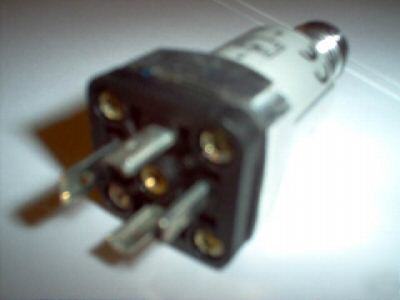
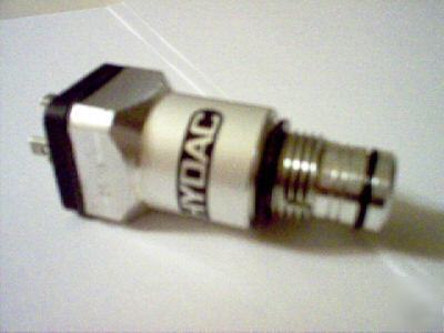
New from the box. Inventory surplus. Clogging Indicators Model VM3-C.0 OR VM5-C.O Clogging indicators are warning devices that signal visually and/or electrically that the filter element is filled with contaminants and should be changed or cleaned. These devices activate (trip) when the flow of fluid causes a pressure drop across the filter element that exceeds the indicator setting. In filters that incorporate bypass valves, contaminated fluid will bypass the element if the operator does not respond to the indicator warning signal within a reasonable time. In non-bypass filters, if the indicator warning is not heeded, the pressure across the filter will build up to the point where system performance is degraded, the element fails, or the system relief valve is actuated. The indicator is set to trip well before the element becomes fully clogged (14 psid / 1 bar lower than bypass), thereby giving the operator sufficient time to take corrective action. The indicator warning may be a visual signal at the filter site (pop-up button, light, etc.); or, some form of signal at a remote location (trouble light, sound alarm, etc.). In some critical applications, where contamination is intolerable, the signal from the indicator may be used to shut down the system so that personnel must immediately service the unit. Some users install filters without indicators, preferring instead to change and/or clean elements according to a fixed time schedule – or based on number of hours of operation. There is some risk in utilizing this approach. It may be difficult to establish a reliable schedule for installing new elements because the rate of dirt ingression is not known, and, in fact, may vary from time-to-time and from machine-to-machine. Use of a clogging indicator has two main benefits: first, it eliminates the need to guess when the element will clog; second, it avoids the unnecessary cost of replacing elements too soon. In a majority of applications, a HYDAC indicator is set to trip at 15 psid (1 bar) below the bypass valve cracking pressure; or, for a non-bypass filter, at 15 psid below the element design changeout pressure. Typically, a HYDAC pressure filter bypass valve begins to crack at 87 psid (6 bar), so the indicator is set to trip at 72 psid (5 bar). A HYDAC return filter ordinarily begins to bypass at 43 psid (3 bar), so the indicator is set to trip at 29 psid (2 bar). Consequently, the operator has a period of time in which to change or clean the element before the bypass valve opens and passes contaminated fluid to sensitive components downstream of the filter. Typically, the time from indication to bypass is 5-15% of the the element as soon as the indicator trips. Non-standard indicator settings are often employed for various reasons. For instance, in lubrication systems, filters may not be allowed to have a high pressure drop, therefore, the indicator may be set to trip at less than 15 psid. When the filter is installed on the suction side of a pump, it is a common practice to limit the ∆P across the filter to 3 psid, and to set the indicator at a correspondingly low amount. Filter assemblies may be ordered with or without indicators. When ordered with an indicator, the assembly model code includes a letter symbol for the indicator, such as B, C, or D. When ordered separately, an indicator has its own complete model code, as described subsequently in this brochure. A type B or BM visual indicator is suitable when only a local warning is required. When it is necessary to signal a remote warning device, control panel, or PLC, one of the electric switches should be specified. Various kinds of switches are available to provide a range of electrical configurations, contact ratings, and connections. The D indicator incorporates a switch and built-in light for both local and remote warning signals. Electric Switch that provides a contact operation to control a warning device or indication at a remote control station. Several models offer differing electrical ratings, contact configurations, and types of connections Differential Pressure Indicators for Pressure Filters and Inline Return Filters Model Code 1) VM2B.1 2) VM5B.1 1) VM2BM.1 2) VM5BM.1 1) VM2C.0 & VM2C.1/T... 2) VM5C.0 & VM5C.1/T... Applicable Filters 1) RFL/RFLD, LFM, NF, NFH/NFHD 1.1 2) LF 30-660, LPF 160-280 DF-AFA, MDF 1) RFL/RFLD, LFM, NF, NFH/NFHD 1.1 2) LF 30-660, LPF 160-280 DF-AFA, MDF 1) RFL/RFLD, LFM, NF, NFH/NFHD 1.1 2) LF 30-660, LPF 160-280 DF-AFA, MDF Green or red display indicates when element is clean or 100% clogged Visual: Green or red display indicates when element is clean or 100% clogged Electric: Electric switch activates to indicate 100% Port Connection G1/2 G1/2 G1/2 Adapter not applicable not applicable not applicable Housing Material aluminum aluminum aluminum Seals nitrile (NBR) - standard fluoro-rubber (FKM) ethylene propylene (EPR) nitrile (NBR) - standard fluoro-rubber (FKM) ethylene propylene (EPR) nitrile (NBR) - standard fluoro-rubber (FKM) ethylene propylene (EPR) Weight 0.12 lbs (55 grams) 0.12 lbs (55 grams) 0.33 lbs (150 grams) 3000 psi (210 bar) 3000 psi (210 bar) 3000 psi (210 bar)Trip Pressure (or Indication Range) 29 psi (2 bar) -10% (standard for RFL/RFLD & LFM) 12 psi (5 bar) -10% (standard for LF, LPF, DF-AFA, & MDF) 29 psi (2 bar) -10% (standard 72 psi (5 bar) -10% (standard for LF, LPF, DF-AFA, & MDF) 29 psi (2 bar) -10% (standard for RFL/RFLD & LFM) 72 psi (5 bar) -10% (standard for LF, LPF, DF-AFA, & MDF) not available not available Option: Below 70°F or 100°F Temperature Range -22°F to 250°F (-30°C to 121°C) -22°F to 250°F (-30°C to 121°C) -22°F to 250°F (-30°C to 121°C) — — 250 VAC Maximum Induction-free Power Rating — — 5 A at 250 VAC 3 A at 12,24 VDC 1 A at 60 VDC Electrical Connection — — PG 11 (steel conduit thread ø 18.6 mm x 18 threads/in.) — — Normally Open and Normally Closed Contacts (SPDT) Insulation — — IP65 Other Electrical Data — — See Type C schematic on page 211 cRUus Rating — — 3A, 250VAC, N.C. Contact 4A, 250VAC, N.O. Contact 4A, 250VAC, (please look at our rules and privacy policy) |
Elba_watts@modularparts.com (Elba Watts) for more information. This email will be sent to Elba Watts' actual email address.

